
Driving the future of nanopositioning
As experts in high speed, high performance applications, our stages can operate at bandwidths over 40% of the stage resonant frequency, four to five times faster than similar systems. The exceptionally low noise control system is important for applications where high resolution, precision and stability are paramount.
Our focus on leading performance is based on class-leading work in stage mechanical design, controller electronics, and control software.
Much of our latest innovation relates to enhanced control to enable high speed imaging (velocity control) and AFM performance for longer range stages (Spatial correction).
Digital controls
Piezo nanopositioning systems require extremely high position resolution in the nanometer and sub-nanometer range with very fast response in the sub-millisecond range. Queensgate’s nanopositioning controllers are fully digital providing numerous improvements over older analogue control and maximizing the performance of high-speed stages with a range of innovative features.
- Low electronic noise. The low noise design allows stage position noise as low as a few tens of picometres.
- High power rating, -30 to +150V drive with 120mA continuous current as standard.
- High-order linearization (4th or higher order) and superior resolution.
- Improved tuning and custom settings for challenging applications
- High speed interfaces for high speed communications.
- Digital signal processing with 24 bit data resolution.
- Fast 20μs control loop update for high speed applications.
- Waveform generators to simplify complex stage routines. This includes a full range of S-curve profiles for smooth acceleration and deceleration, staircase-step move sequences for Z-stacking or raster scans, and a variety of other move types.
- Stage EEPROM providing full plug and play allowing stages to be used with any Queensgate controller
- Digital Notch filtering – Two notch filters are provided as standard; with digital control, these filters can be set extremely precisely. These combined with good stage mechanical design ensure the resonances remain consistent even under substantial changes of load. This is particularly important for applications such as microscopy where loads can vary in day to day use.
Digital Notch Filtering – Fastest step settle times
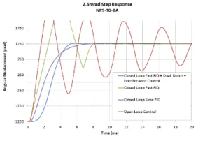
Figure 1: Showing the impact of trajectory control on the step settle time of a tip tilt stage
Velocity Control
Many applications such as surface scanning rely on the stage following a constant trajectory. Tracking a moving command (such as a raster-scan ramp or a sine wave), will always have some residual error. This is an unavoidable feature of the mathematics behind closed-loop position control, and the greater the velocity and acceleration required, the greater the error. To solve this problem, Queensgate developed a control system that provides closed-loop control of position, velocity, and acceleration
Closed-loop velocity control enables high-quality (high resolution) imagery at raster speeds in excess of 4 mm/s over longer travel ranges.
- Stage can accommodate larger samples (and payloads)
- The scan area can increase significantly obviating the need for data stitching
- The linearity of the position data obtainable when interpolating from the constant velocity allows high quality images to be captured.
Demonstration of closed loop velocity control for fast imaging techniques using high-speed AFM
The study covers AFM as a specific example of where this can be applied. The same technology is equally applicable for other areas requiring measurements at accurate intervals while a nanopositioning stage moves continuously. Examples of these applications are confocal microscopy, surface smoothness scanning, or optical alignment.
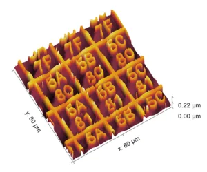
Figure 2: Images were captured at 2000 μm/s, 1nm resolution, 250 scan lines, acquisition time 40 seconds. x= 80μm, y=80μm, z=22μm. (Note: The sample had been damaged previously, with some clearly-visible scratches across it.)
Spatial Positioning Correction for Multi-axis Nanopositioning Stages
All moving systems have some unwanted motion in other axes. For a multi-axis stage, this causes positioning errors in all motion axes. This is most significant for longer-range stages, and can be the principal limiting factor in positioning accuracy. Significant improvements in spacial positioning errors for multi-axis stages are achieved with a measurement and calibration methodology. Improvement on the larger multi-axis stages achieve performance suitable for use in high precision applications such as AFM.
The study shows the development of a spatial error correction for a 600x600x600 µm XYZ stage which delivers a consistent positioning performance for the entire closed loop range in all axes.
Download the Spatial Positioning Correction for multi-axis nanopositioning stages paper.
Calibration re-centering and Diagnostics
Substantial changes in load and environmental conditions can cause an offset in the stage range. The option of calibration re-centring on power up corrects for this preventing range clipping. This can be important for microscopy applications where different objective lenses may be used on an objective positioner or where incubators may be used on a sample scanner. In addition advanced diagnostics protect the electronics in use and are used to troubleshoot issues with stages.
Get in touch
If you have a nanopositioning project we’d be happy to discuss your requirements. Please contact us here.


